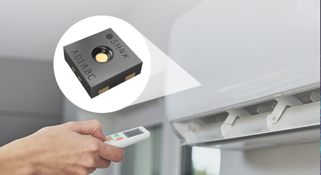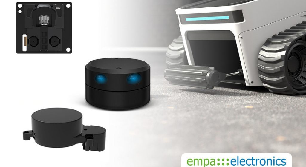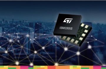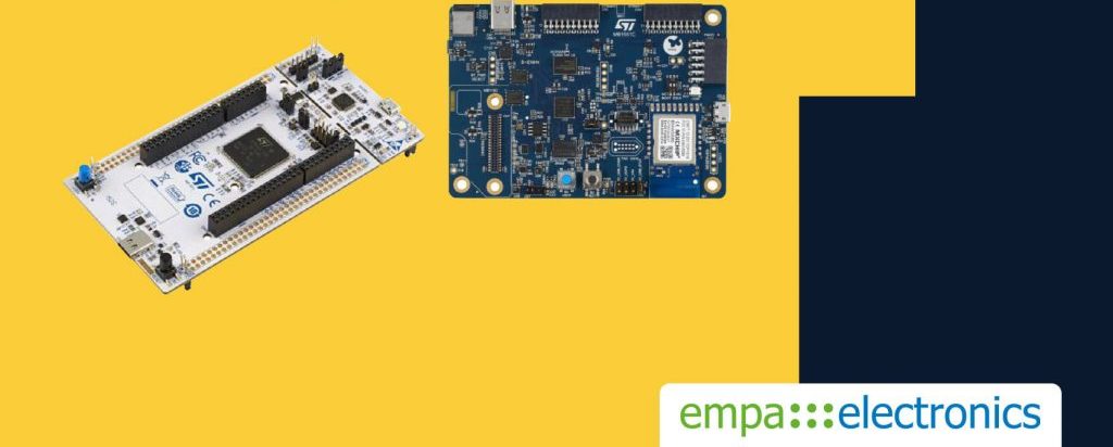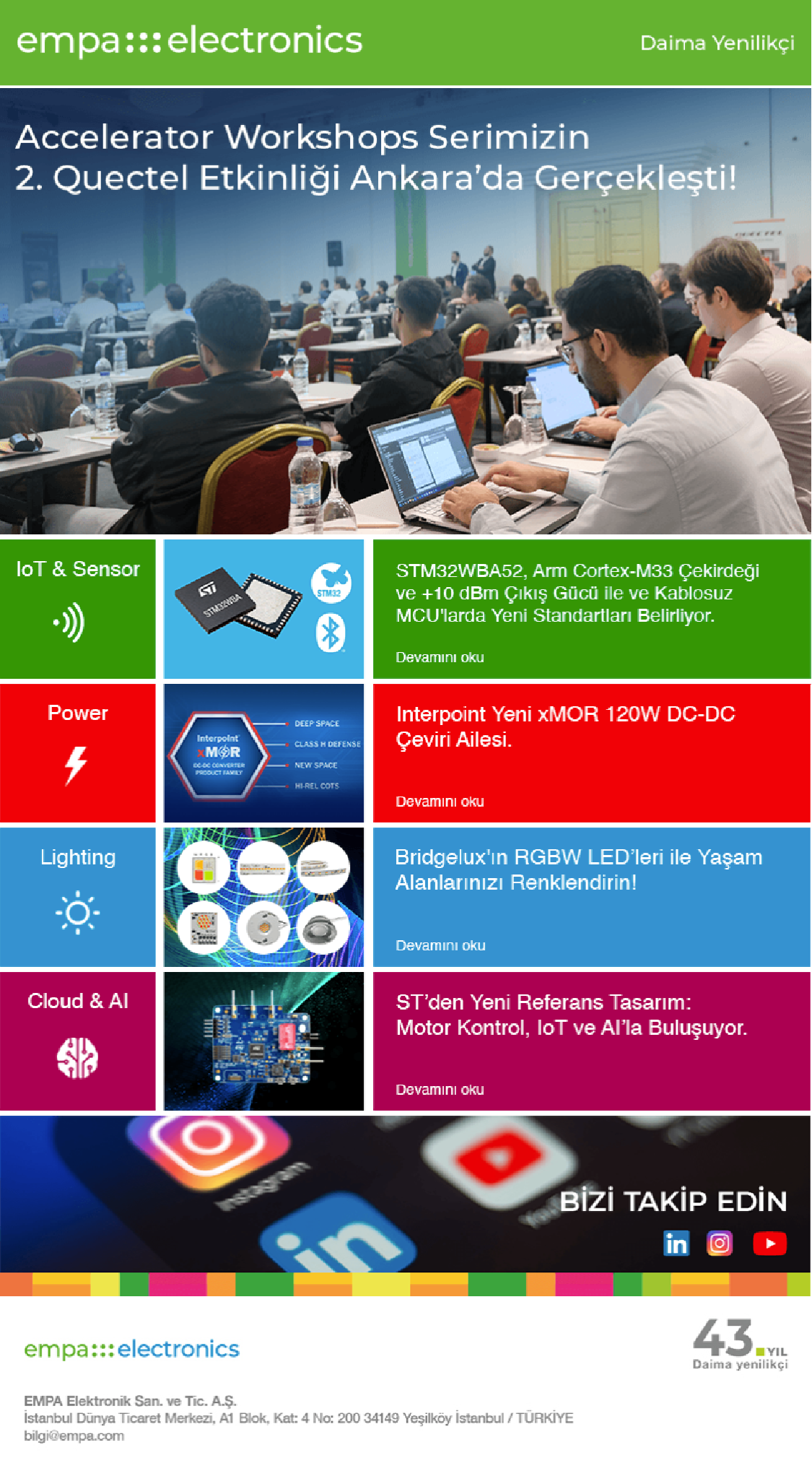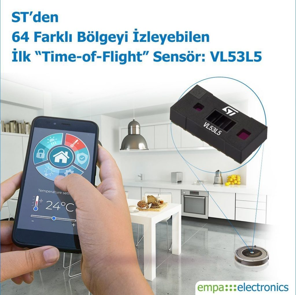


IoT & Sensor
We can provide end-to-end solutions to meet the requirements of various markets with our leading manufacturers and our teams specialized in IoT.
Read More>
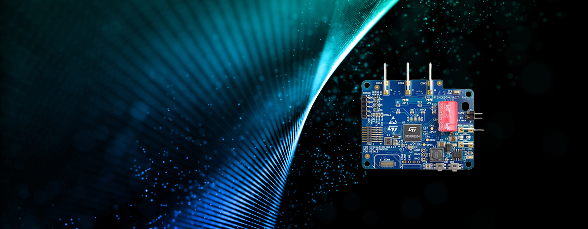
Power
In recent years, we have been providing solutions to the growing power electronics market with our leading, innovative, and alternative product lines, ranging from discrete components to module products.
Read More>
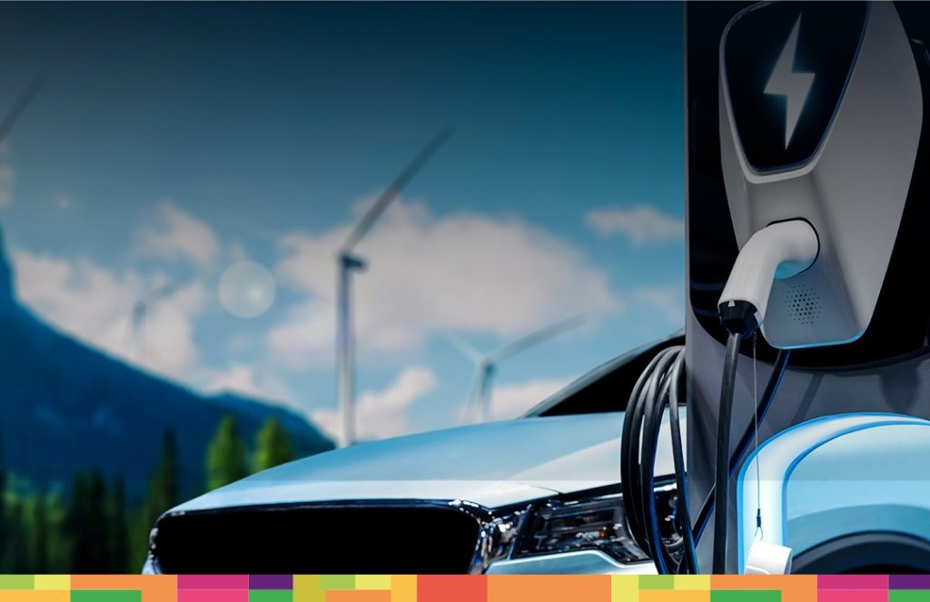
E-Mobility
We offer support through solutions from leading companies, bringing them together with the rapidly developing automotive industry in our country, contributing to the development of our country and the future of our world.
Read More>
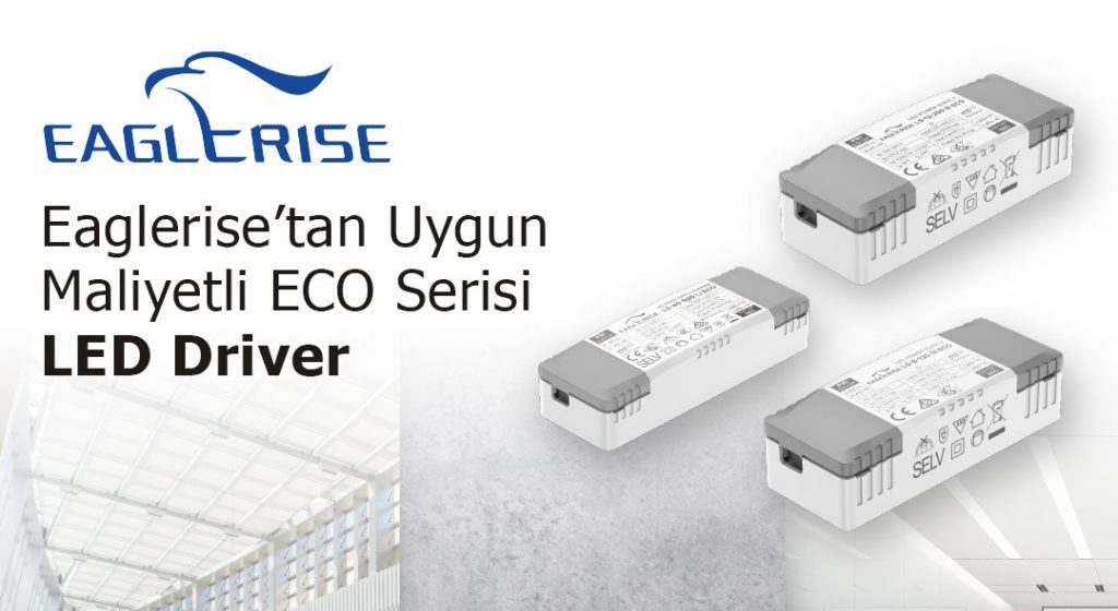
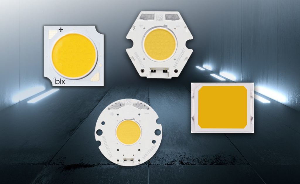
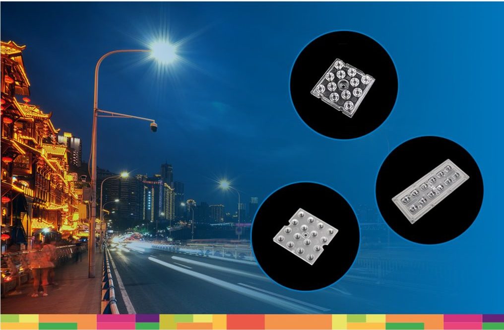
Lighting
We combine our extensive experience in electronics with the rapidly evolving automotive industry in our country, contributing to the development of our country and the future of our world.
Read More>
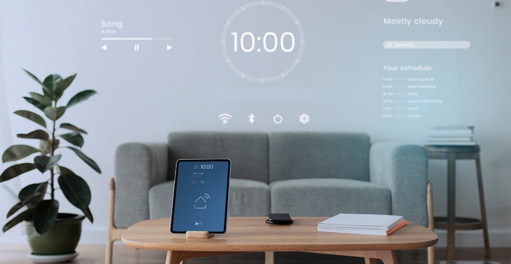
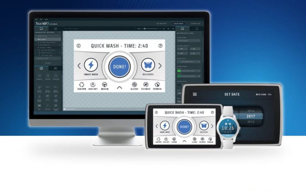
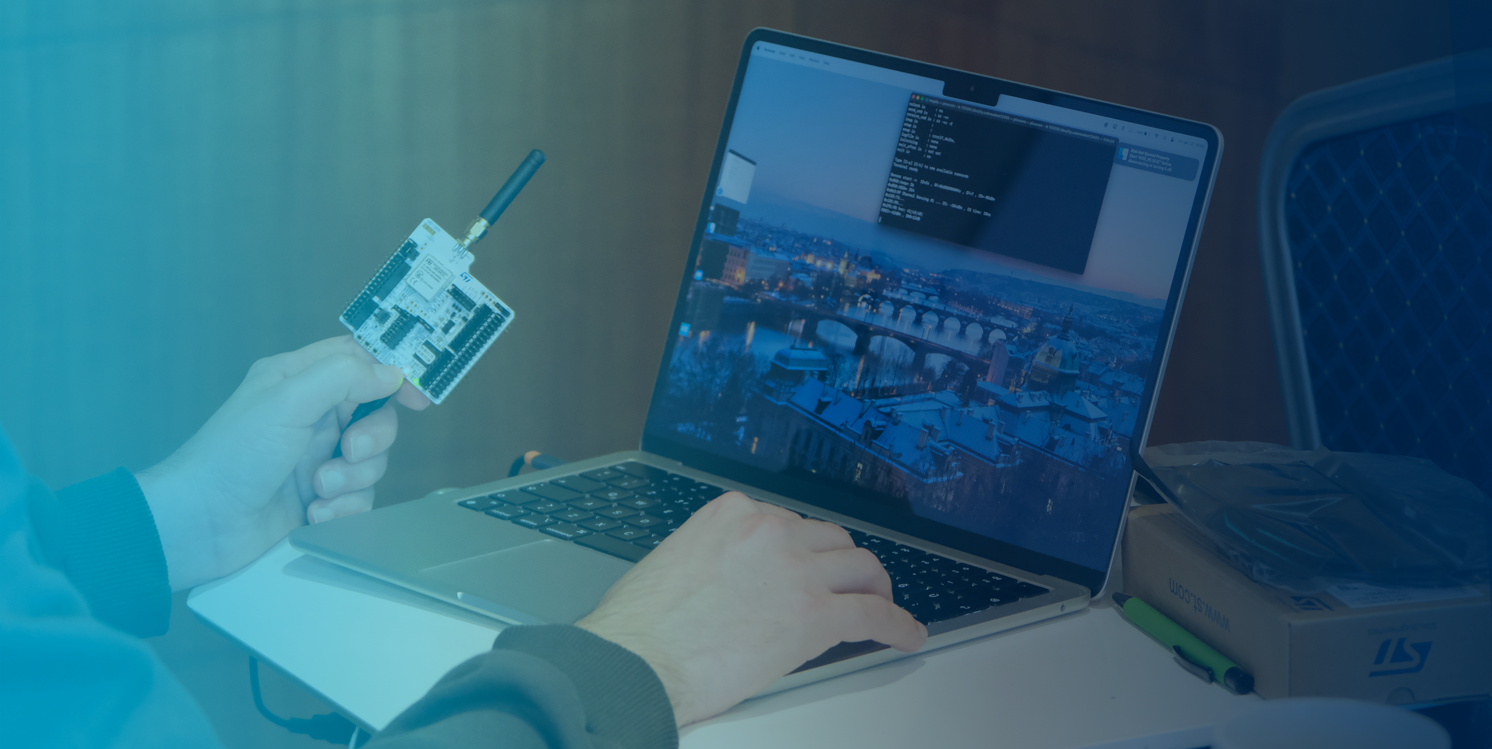
AI & Cloud
We create advanced designs and share them with our customers, enabling them to accelerate their digital transformation and innovation processes, and make a difference in their respective industries.
Read More>
Aerospace & Defance
We are working on bringing critical technologies necessary for the realization of domestic and national defense industry projects to our country and supplying sub-components to companies operating in this field.
Read More>